|
|
|
|
|
|
Product Details:
Payment & Shipping Terms:
|
| Material: | C.S/SS | Seal: | NBR/FKM |
|---|---|---|---|
| Pressure: | 315 Bar | Fluid Temperature Range: | -30 To +80 (NBR Seal)/-20 To +80 (FKM Seal) ℃ |
| High Light: | hydraulic lever control valves,hydraulic proportional control valve |
||
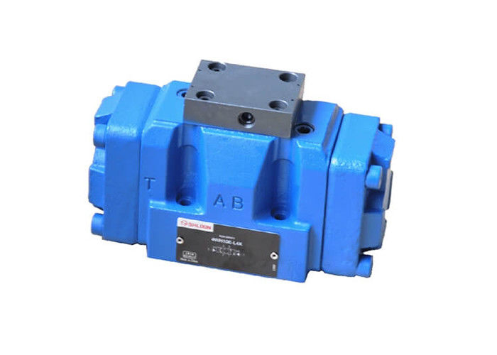
4/3, 4/2 and 3/2 directional valve with fluidic actuation
Type WH 10, 16, 25 and 32
Features:
– Valves used to control the start, stop and direction of a fluid flow
– Hydraulic operation (WH)
– Porting pattern conforms o DIN 24 340 form A,ISO 4401 and CETOP-RP 121H
Function and configuration
Valves of type WH are directional spool valves with hydraulic operation. They control the start, stop and direction of a flow.
1. Spring-centered valve
The main spool (2) is kept in the centre position by the return springs (3). If external control fluid enters main valve (1) from port X then enters left spring chamber (5) via cover (4), the main spool is pushed into the switching position. The oil of right spring chamber returns to tank from port Y. When the control fluid is cancelled, the main spool returns to centre position under the action of right spring force. And if the control fluid enters from port Y, then the main spring moves to left to switching direction and the oil of left spring chamber returns to tank from port X.
Structure chart of valve type WH25 with spring-centered.
![]()
Structure chart of valve type WH25 with spring-centered
2. Hydraulic-centered valve
Pressure fluid acts on both sides of main spool (2) and main spool (2) is fixed by a locating sleeve. If one side of the main spool is unloaded, then it moves under pressure at opposite side to switch direction. If the control fluid enters left chamber of main valve from port X, the main spool moves right, the fluid of right chamber returns to tank from port Y; and if the control fluid enters right chamber from port Y, the main spool moves left, the fluid of left chamber returns to tank from port X. Internal leakage oil directly returns to tank from port L.
![]()
Structure chart of valve type WH25 with spring-centered
Switching time adjustment (see WEH) Flow area when valve is in central position (see WEH)
Characteristic curve (see WEH) Technical data (see hydraulic part of WEH technical data)
Performance limits (see WEH) Additional device (stroke adjustment) (see WEH)
Specifications
![]()
Symbols
![]()
Notes:
1. All control oil are external supply and external drain.
2. Control pressure in port X and port Y is not allowed to exceed 250 bar.
Connection dimensions and sub-plate
1. The same size of type WH and type WEH share same installation, connection dimensions and sub-plate.
2. Regarding dimensions, only the height of type WH is different from that of type WEH.
For type WH, there is a cover (height: 12mm) on top of the main valve.
Also switching time adjusted can be topped with a height of 40mm. Details see WEH.